News
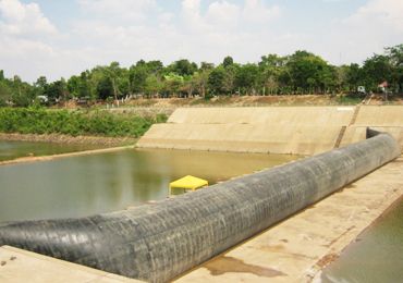
Inflatable rubber dams are hydrostatic structures consisting of a fabric-reinforced rubber bladder anchored to a concrete dam structure with clamping plates. This arrangement forms a sealed internal space that can be filled with either air or water.
In both air-filled and water-filled rubber dams, the membrane establishes a balance between the internal pressure and the external water load. By adjusting the filling volume, operators can change the bladder height and control the water-retention and discharge sections according to the hydraulic requirements of the project.
The pumps and valves are operated from a control house. Equipment for water-filled systems is generally installed in underground shafts, while air-filled systems normally use an above-ground control house. The control system maintains the specified retention set point, and the duration of inflation and deflation can be adjusted.
Air or water is supplied to the rubber dam through pipes connected to the control system. When the water level in the retention area rises above the set point, the bladder gradually deflates. Complete deflation clears the full dam opening and increases the available discharge capacity.
When the water level falls, the bladder is inflated again. This operating cycle keeps the upstream water level close to the specified retention set point.
The selection of air or water as the filling medium depends on the project requirements. Operating speed, overtopping behavior, climate, water quality and discharge measurement should be evaluated during the planning stage.
Operating Factor | Air-Filled Rubber Dams | Water-Filled Rubber Dams |
Overtopping | Even overtopping when operating at 95%–100% of the maximum bladder height | Even overtopping in every operating mode |
Partial-height operation | A V-shaped depression forms below approximately 95% of the maximum bladder height | The bladder crest remains horizontal during partial operation |
Span control | Individual spans can be controlled separately | Individual spans can be controlled separately |
Inflation and deflation time | Approximately 5–30 minutes, depending on dam size | Approximately 1–4 hours, depending on dam size |
Filling medium | Ambient air | Generally river water; water-quality improvement measures may be required |
Winter operation | No icing of the filling medium | Effective anti-icing measures are required during cold seasons |
Discharge calculation | Possible at approximately 95%–100% of the maximum bladder height | Discharge and residual water volume can be calculated from approximately 25%–100% of the maximum bladder height when bladder-height detection is used |
Operation in hot regions | — | Reduced heating of the rubber bladder may contribute to a longer service life |
Bladder damage | — | Lower loss of filling medium if the rubber bladder is damaged |
An air-filled rubber dam is raised and maintained by the air pressure inside the bladder. During inflation, a blower installed in the control room on the riverbank supplies air to the rubber dam through a regulating pipe.
The inflated bladder, including its sidewall sections, is completely airtight. As inflation continues, the bladder rises and impounds the upstream water.
Deflation is carried out using electrically or pneumatically controlled valves. All valves can also be operated manually. For smaller dams, the complete control system may be installed in a thermally insulated and heated outdoor cabinet.
An air-filled rubber dam is equipped with sensors for safe operation, accurate positioning and continuous monitoring. These sensors measure the water level in the retention area and the internal pressure of the bladder.
The inside of the bladder is also monitored for condensate formation or the intrusion of outside water. Internal pressure is measured separately for each span, so individual measuring pipes are installed between the spans and the control house.
Up to a deflation level of approximately 90%–95% of the maximum bladder height, an air-filled rubber dam behaves similarly to a water-filled system. When it is lowered further, a V-shaped depression forms and allows greater overtopping through the depressed area.
Air-filled rubber dams therefore do not produce overtopping as evenly as water-filled rubber dams during lower operating positions. Depending on the site conditions and required discharge pattern, this may provide either advantages or disadvantages. The control system maintains the specified retention set point by adjusting the internal air pressure and bladder height.
As a general rule, inflatable rubber dams may be used at sites where downstream water is retained.
When there is no downstream retention, the air-filled bladder may be fixed to the dam body using only one upstream anchoring line. If the retained downstream water reaches the non-overtopped dam, a second fixing line may be required.
In a water-filled rubber dam, the internal pressure is created according to the principle of communicating vessels. A water column in the control shaft is connected to the inside of the bladder through a regulating pipe.
The height of the water column determines the internal pressure and therefore the operating height of the inflated bladder.
The control shaft may be fixed or height-adjustable. A height-adjustable control shaft consists of a base pipe and a water bag.
One or more filling pumps supply water to the control shaft and the inside of the bladder. The water is taken from a supply shaft, which is generally connected to the upstream water through one or more pipes.
The bladder is inflated by feeding water into the control shaft. When the internal pressure exceeds the combined external forces created by the bladder weight and water load, the bladder begins to rise. The inflated bladder then retains water in the upstream area.
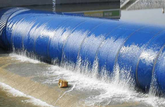
The crest of a water-filled rubber dam remains horizontal even when the bladder is only partially filled. Overtopping water is therefore distributed evenly across the width of the dam.
Measured parameters may include the upstream retention level, downstream water level and bladder height. These measurements allow the discharge rate to be calculated within a specified operating range. The calculated discharge can then be incorporated into the control system as an additional control parameter.