News
Efficient water management depends on the ability to regulate flow rates and water levels under changing operating conditions. An automatic sluice gate system combines a movable gate, sensors, actuators and a control unit to adjust the gate opening without continuous manual intervention. These systems are widely used in irrigation canals, drainage networks, reservoirs, flood-control projects, hydropower facilities and water treatment plants.
Unlike a manually operated gate, an automated sluice gate can respond to changes in upstream water level, downstream demand, rainfall, flow rate or a predefined operating schedule. It can also be connected to a Supervisory Control and Data Acquisition system, commonly known as SCADA, for centralized monitoring and remote operation. Automated gates can work independently or as connected control points across a larger water network.
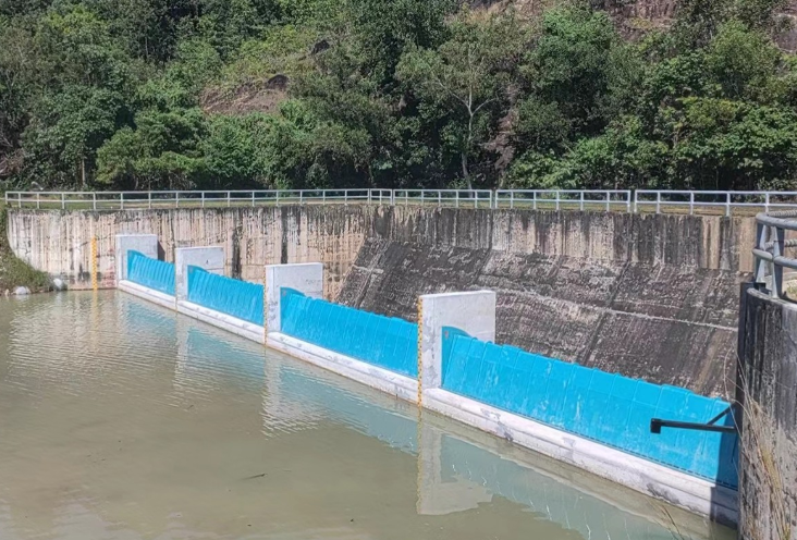
A sluice gate controls water by raising or lowering a movable panel within a fixed frame. When the gate rises, water passes beneath it. When the opening is reduced, the discharge decreases and the upstream water level usually rises. Fully lowering the gate can isolate a channel or stop the flow for maintenance and emergency control.
A typical automatic sluice gate system includes:
· A gate frame and movable gate leaf
· Seals, guides and embedded mounting components
· An electric or hydraulic actuator
· Upstream and downstream water-level sensors
· Flow, pressure or rainfall sensors where required
· A programmable logic controller, or PLC
· A local control cabinet
· SCADA or remote communication equipment
· Limit switches, position indicators and overload protection
· Backup power or a manual operating mechanism
The gate may be manufactured from stainless steel, coated carbon steel, aluminium or cast iron. Material selection depends on gate dimensions, hydrostatic pressure, water quality, corrosion exposure, leakage requirements and expected service life.
The control process begins with field sensors. Water-level transmitters, ultrasonic sensors, pressure sensors or flow meters continuously collect operating data. These signals are sent to the PLC, which compares the measured values with the target setpoint.
If the upstream level rises above the setpoint, the controller can command the actuator to increase the gate opening. If the water level falls, the gate can close gradually to conserve water. For flow-control applications, the controller repeatedly adjusts the opening until the measured discharge reaches the required value.
For a free-flowing rectangular sluice gate, discharge may be estimated using a simplified relationship:
Q = Cd × b × a × √(2gh)
Where:
· Q is the discharge rate
· Cd is the discharge coefficient
· b is the gate width
· a is the gate opening
· g is gravitational acceleration
· h is the effective upstream head
Actual performance can be affected by downstream water level, submerged-flow conditions, gate geometry, approach velocity and sediment accumulation. Therefore, important projects should use site-specific hydraulic calculations and calibrated sensor data instead of relying on the simplified equation alone. Research on multi-gate sluice structures also shows that local flow conditions can affect scour, navigation and gate vibration even when the total discharge is similar.
The system maintains a target upstream or downstream water level. This mode is commonly used in reservoirs, canals, drainage channels and pumping stations.
The gate opening is adjusted according to data from a flow meter or a calculated gate-discharge relationship. This allows controlled water delivery to irrigation zones, treatment processes or industrial users.
The gate operates according to predefined times. Scheduled operation is useful where water must be released during specific irrigation periods or according to an established reservoir management plan.
Operators can issue opening and closing commands from a control room through a SCADA interface. Gate position, water level, actuator status and system alarms can be viewed remotely.
The PLC can trigger a predetermined response when it detects abnormal water levels, equipment overload, communication failure or another emergency condition. The appropriate fail-safe position—open, closed or held in place—must be determined during engineering design.
Automatic sluice gate systems can support several types of water infrastructure.
In irrigation networks, they regulate canal levels and distribute water among branches according to crop demand. Automated control helps reduce unnecessary overflow and improves the consistency of water delivery.
In flood-control and drainage projects, gates can respond to rising river levels, heavy rainfall or storage-basin conditions. Coordinated operation allows water to be temporarily retained, diverted or released according to the available downstream capacity.
Water and wastewater treatment plants use sluice gates to isolate channels, regulate inflow and direct water between treatment units. They may be installed at screen channels, sedimentation tanks, distribution chambers, pumping stations and discharge outlets.
At dams, reservoirs and hydropower facilities, automated gates support controlled releases, turbine intake management, environmental flow requirements and emergency drawdown procedures.
They are also used in aquaculture, industrial water systems, tidal-control structures and urban stormwater networks.
The primary advantage is faster and more consistent response. A sensor-based system can make incremental adjustments as hydraulic conditions change, reducing dependence on operators travelling to remote gate locations.
Automation also provides:
· More stable upstream and downstream water levels
· Better allocation of limited water resources
· Remote monitoring of gate position and system condition
· Reduced manual workload at isolated or hazardous sites
· Automatic alarms and event records
· Faster response during floods or equipment failures
· Integration with pumps, weather stations and reservoir controls
· Historical data for operational analysis and maintenance planning
The system should still allow local and manual operation. Automation improves control, but it does not remove the need for trained operators, inspections or emergency procedures.
An automatic sluice gate should be selected according to actual hydraulic and site conditions. Essential project information includes:
· Clear opening width and height
· Maximum upstream and downstream water levels
· Seating or unseating water pressure
· Required flow range
· Allowable leakage rate
· Water quality, salinity and corrosion exposure
· Sediment, debris and floating-material conditions
· Required opening and closing speed
· Available power supply
· Communication protocol
· Installation method and civil structure dimensions
· Required environmental protection rating
· Local operating and emergency requirements
The actuator must provide sufficient thrust to overcome the gate weight, seal friction, hydrostatic force and possible debris resistance. Oversizing without proper speed and torque control can damage the stem or gate structure, while undersizing may prevent the gate from operating under maximum head.
For remote sites, solar power, battery backup or an emergency generator may be considered. Communication can use fibre-optic cable, Ethernet, radio, cellular networks or other project-approved systems.
Routine maintenance is necessary even when the gate is fully automated. Operators should inspect the seals, guides, stem, lifting mechanism, fasteners and protective coating. Sediment and debris should be removed before they restrict gate movement.
Level sensors and flow meters require periodic cleaning and calibration. Electric actuators should be checked for moisture ingress, limit-switch accuracy and abnormal current draw. Hydraulic systems require inspection of fluid levels, hoses, cylinders and possible leakage.
The control program should be tested under normal and emergency conditions. Manual operation, backup power, communication-loss responses and high-water alarms should also be verified at planned intervals.
An automatic sluice gate system provides an effective method for controlling water flow, maintaining water levels and responding to rapidly changing hydraulic conditions. Its performance depends on more than the gate itself: accurate sensors, suitable actuators, reliable control logic and proper hydraulic design must work together as one system.
Before selecting a solution, project owners should provide complete information about channel dimensions, design water levels, flow requirements, installation conditions, power availability and control objectives. A properly engineered system can improve water distribution, strengthen flood response and support safer, more efficient operation throughout the life of the water-control project.
Previous: None