News
Dams are engineered barriers constructed across rivers or streams to impound water for irrigation, hydropower generation, flood control, and recreation. Reservoirs formed by dams serve as storage basins that regulate downstream flows and provide critical water supply during dry periods. Understanding the hydraulics of these structures is essential to ensure their safety, efficiency, and environmental compatibility.

The behavior of water in dam systems is governed by the Bernoulli equation, which relates pressure, velocity, and elevation head in a flowing fluid. This principle allows engineers to calculate energy transformations between potential and kinetic forms, vital for designing outlets, penstocks, and turbines.
The velocity of water discharging from a dam outlet can be estimated using Torricelli’s law, a special case of Bernoulli’s equation, where velocity equals the square root of twice the product of gravitational acceleration and head height. Accurate prediction of outlet flow rates is critical for managing downstream water levels and preventing erosion.
Hydrostatic pressure increases linearly with water depth and can be expressed as p = ρgh, where ρ is water density, g is gravitational acceleration, and h is the depth below the water surface. For a vertical surface with a water depth of H, the resultant horizontal force per unit width is P = 1/2ρgH² and acts at approximately H/3 above the base. This relationship explains why the lower sections of dams, gates, retaining walls, and outlet structures are designed for substantially higher loads than the upper sections.
Hydrostatic pressure is not the only hydraulic load considered in dam design. Engineers must also evaluate uplift pressure beneath the structure, tailwater pressure, wave action, sediment pressure, ice loads, and hydrodynamic forces generated during earthquakes. The way these forces are transferred depends on the dam type.
| Dam Type | How the Water Load Is Resisted | Main Hydraulic Design Checks |
|---|---|---|
| Gravity dam | The weight of the concrete or masonry body resists horizontal water pressure | Sliding, overturning, uplift pressure, foundation bearing capacity, and spillway discharge |
| Arch dam | Water loads are transferred laterally through the curved dam body to the rock abutments | Abutment stability, stress distribution, joint movement, and reservoir load variation |
| Earthfill dam | Compacted soil mass and internal shear strength provide stability | Seepage, pore-water pressure, internal erosion, slope stability, freeboard, and overtopping protection |
| Rockfill dam | A rock shell provides stability while a clay core or concrete face controls leakage | Settlement, face or core integrity, seepage collection, joint movement, and foundation deformation |
The structural form should therefore be selected only after confirming valley geometry, foundation conditions, available construction materials, reservoir depth, flood discharge requirements, and acceptable seepage performance.
Reservoirs are subject to wind-generated waves and thermally driven density currents, which affect mixing, water quality, and shoreline stability. Engineers analyze these phenomena to design intake structures and mitigate shoreline erosion.
Sediment accumulation reduces reservoir storage capacity and affects hydraulic performance. Drawdown flushing, pressure flushing, and turbidity current venting are employed to manage sediment deposition and maintain capacity. Best practices for hydraulic flushing include optimizing drawdown rates and selecting appropriate venting configurations. Case studies using HEC-RAS modeling illustrate effective sediment management in reservoirs.
Reservoir capacity is divided into operating zones according to elevation and intended use. These zones are defined through topographic surveys and elevation-area-capacity curves rather than by total reservoir volume alone.
◆ Dead storage lies below the lowest usable outlet. It cannot normally be released by gravity and is often reserved for long-term sediment accumulation.
◆ Active or conservation storage extends from the minimum operating level to the normal pool level. It supplies irrigation, municipal and industrial water, hydropower generation, and other scheduled releases.
◆ Flood-control storage lies between the normal pool level and the maximum permitted water level. This volume is kept available to temporarily retain flood inflows and reduce downstream peak discharge.
◆ Surcharge storage may be used temporarily during an extreme flood, but only within the hydraulic and structural limits established for the dam and spillway.
Reservoir operation follows a water balance in which the change in storage equals inflow minus controlled releases, spill, evaporation, and seepage losses. Operating rules must account for forecast inflow, seasonal demand, environmental flow requirements, outlet capacity, gate movement limits, downstream channel capacity, and the rate at which the reservoir level can safely rise or fall.
During wet seasons, sufficient flood-control capacity must be maintained before major inflows arrive. During dry periods, releases are coordinated to preserve essential water supply and downstream ecological flow. Because sediment deposition changes the elevation-capacity relationship over time, bathymetric surveys should be used to update operating curves and the estimated remaining storage volume.
Spillways safely convey excess floodwater over or around dams. The configuration of spillway approaches—deep, shallow, or confined—influences contraction coefficients and nappe profiles, affecting flow stability. Chute designs may use diverging or converging sidewalls, with sidewall heights sized to contain the design flood flow while accounting for air entrainment and wave effects.
Downstream of spillway chutes, stilling basins dissipate flow energy to prevent scour. Basin geometry is tailored to flow conditions and sediment load, ensuring hydraulic jumps form within the structure for efficient energy dissipation.
Outlet works provide controlled releases for water supply, irrigation, environmental flow, reservoir drawdown, sediment management, and emergency lowering. A typical outlet system may include an intake structure, conduit or tunnel, control gate or valve, air vent, downstream transition, and energy-dissipation structure.
For preliminary evaluation of free discharge through an opening, the flow rate can be estimated using:
Q = CdA√(2gH)
where Q is discharge, Cd is the discharge coefficient, A is the effective opening area, g is gravitational acceleration, and H is the effective hydraulic head. Final discharge calculations must also account for entrance and friction losses, gate opening, tailwater submergence, conduit geometry, sediment accumulation, and changing reservoir levels.
The hydraulic design must check flow velocity, pressure fluctuations, cavitation risk, vibration, air demand, debris blockage, sediment abrasion, and downstream erosion. Gates and valves should be capable of regulating both small continuous releases and higher drawdown flows without operating for long periods in unstable opening ranges.
Safe operation also depends on reliable gate-position feedback, water-level measurement, emergency operating procedures, inspection access, and an appropriate backup operating method. Where several gates operate together, opening sequences should be coordinated to avoid rapid downstream level changes, asymmetric loading, and excessive local scour.
Guidance manuals provide standards for designing navigation dams, emphasizing factors like ice passage, debris management, and emergency operations. Hydraulic steel structures within dams, such as gates and valves, are designed using Load and Resistance Factor Design (LRFD) principles to ensure reliability under variable loading.
Seepage through a dam, its foundation, or its abutments must be controlled and monitored throughout the structure’s service life. The objective is not always to eliminate seepage completely, but to keep seepage pressure and flow within the limits assumed in the design.
Concrete dams may use foundation grouting, cutoff systems, drainage galleries, relief holes, and uplift-pressure monitoring. Earthfill and rockfill dams rely on impervious cores or upstream faces, cutoff trenches or walls, properly graded filters, and drainage zones. Filters must retain particles from the protected soil while allowing water to pass without creating excessive pore pressure. An increase in seepage flow, cloudy discharge, transported soil particles, or a new wet area on the downstream slope can indicate developing internal erosion.
Dam instrumentation commonly includes piezometers, seepage measuring weirs, reservoir and tailwater gauges, settlement monuments, inclinometers, joint meters, strain gauges, temperature sensors, and gate-position sensors. Readings should be evaluated as trends and compared with reservoir elevation, rainfall, seasonal temperature, gate operation, and previous inspection results.
Monitoring thresholds should be connected to defined actions, such as increased observation frequency, engineering review, controlled reservoir drawdown, or emergency response. This approach allows abnormal behavior to be identified before it develops into a hydraulic or structural safety problem.
Water control manuals integrate hydraulic, sediment, economic, and environmental analyses to optimize drawdown alternatives and reservoir operation. Modern approaches incorporate real-time monitoring and adaptive management to balance water supply, power generation, ecological flows, and flood risk.
A thorough grasp of dam and reservoir hydraulics—rooted in fundamental fluid mechanics, enriched by sediment and wave dynamics, and applied through robust spillway and stilling basin design—is indispensable for sustainable water management. By adhering to established design manuals and employing best practices in sediment control and flow regulation, engineers can ensure the long-term safety, functionality, and environmental stewardship of dam infrastructure.
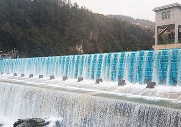
For projects requiring frequent water-level adjustment, controlled flood release, and automated operation, a Hydraulic Elevator Dam may be evaluated based on the required gate height, span arrangement, hydraulic head, discharge rate, and control strategy.
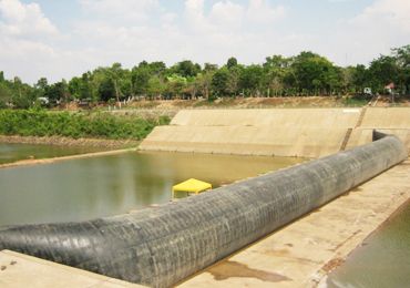
For low-head water retention where the structure should be lowered to reduce obstruction during flood passage, an Inflatable Rubber Dam can be assessed against channel width, inflation method, foundation conditions, debris load, and required inflation or deflation time.
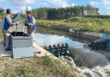
For remote rivers or locations without a stable electricity supply, a Simplified Elevated Dam may provide a manually or diesel-driven water-control option. The allowable gate dimensions, operating frequency, flood-discharge requirements, and site access must still be confirmed for each project.
Before beginning preliminary design, project owners should provide available hydrological records, design water levels, target discharge, river cross-sections, geotechnical information, sediment and ice conditions, and expected operating procedures. BIC’s technical services cover site investigation, feasibility assessment, design consultation, and installation guidance for hydraulic structures.